
So far, I’ve figured out how to read inputs from sensors and controls (buttons) from the Arduino to UE4 (can be found in the blog post titled ‘Arduino to UE4’), and figured out how to trigger the Arduino to execute commands based on UE4 events (can be found in the blog post titled ‘UE4 Event Driven Servos‘), but one thing which I was how to send variables to the Arduino from UE4… Understanding how to do this would enable more control of the Arduino and would allow more interaction possibilities between the two. As my ideal goal would be to control a synchronised virtual/physical camera, it is important to be able to control complex components of the physical world. This could include position in space and overall movement. To achieve this, information must be communicated to the Arduino about the vector movement information of the virtual camera so it can drive motors to position the physical cameras position. Early experiments will be very basic, but the long-term strategy may be to set up a 3 axis rail system (similar to a 3D printer) controlled by three motors to position the camera against a constrained X/Y/Z position. This early proto would constrain movement to translations, not rotations, as rotations would require a powerful gimbal setup to hold the camera’s weight. It is envisioned that early prototypes may be able to drive a simple webcam and synchronise UE4 camera movement with actual camera. In essence, this would be a primitive motion control setup.
This youtube video explains exactly how a motion control setup works within cinematography.
By figuring out how to control this on a prosumer level, leveraging UE4 motion and physical camera motion, a similar result can be gained with splicing both digital and physical elements together within an overall composite. Anyway… enough about why I am trying to figure out how to do this, more onto the Arduino specific stuff and experiments!
Establishing data flow from UE4 to Arduino
To be able to control the motor on the UE4, information about position or movement of elements within UE4 is needed by the Arduino. This information can be processed and manipulated to drive motor rotations/speed/direction. Without being able to send positional values to the Arduino, it would be difficult to control a motion control through movements within UE4. To figure out how this works, a simple test was set up to see if variables are sent through the Send Int node off the UE4Duino plugin node. With a simple if statement with different conditions, we could determine if the correct information was sent to the Arduino, as you cannot actively monitor the I/O of the Arduino while it is being used by UE4.
The test: If the Y position of the object moving within UE4 is between 0-50, it illuminates light 1 only. If between 51-100, it illuminates light 2 only, if between 101-200, it illuminates light 3 only. By setting up this simple test using three LEDs, we could determine if the correct values were being sent to the Arduino. Once this is established, we can consider changing the values to work with motor control values with some additional code and math.
Here is the setup of the Arduino. Three independent LEDs are powered by the OUTPUT of different digital pins, controlled by the simple if statements on the code.

The code simply starts the Serial port, establishes the three LEDs, and leverages IF statements to set the LED to HIGH (on) and LOW (off) depending on which IF condition is true.
const int ledPin1 = 12;
const int ledPin2 = 9;
const int ledPin3 = 3;
int value = 0;
void setup() {
// Establish pins to be output and lights to be off
pinMode(ledPin1, OUTPUT);
pinMode(ledPin2, OUTPUT);
pinMode(ledPin3, OUTPUT);
digitalWrite(ledPin1, LOW);
digitalWrite(ledPin2, LOW);
digitalWrite(ledPin3, LOW);
Serial.begin(9600);
}
void loop() {
// put your main code here, to run repeatedly:
if (!Serial.available()) return;
while(Serial.available()){
value = Serial.read(); // Assigns the value sent from UE4 to the variable called value
// If the value is between 1-50
if (value >0 && value <=50){
digitalWrite(ledPin1, HIGH);
digitalWrite(ledPin2, LOW);
digitalWrite(ledPin3, LOW);
}
// If the value is between 50-99
if (value >=50 && value <100){
digitalWrite(ledPin1, LOW);
digitalWrite(ledPin2, HIGH);
digitalWrite(ledPin3, LOW);
}
// If the value is 100+
if (value >=100){
digitalWrite(ledPin1, LOW);
digitalWrite(ledPin2, LOW);
digitalWrite(ledPin3, HIGH);
}
}
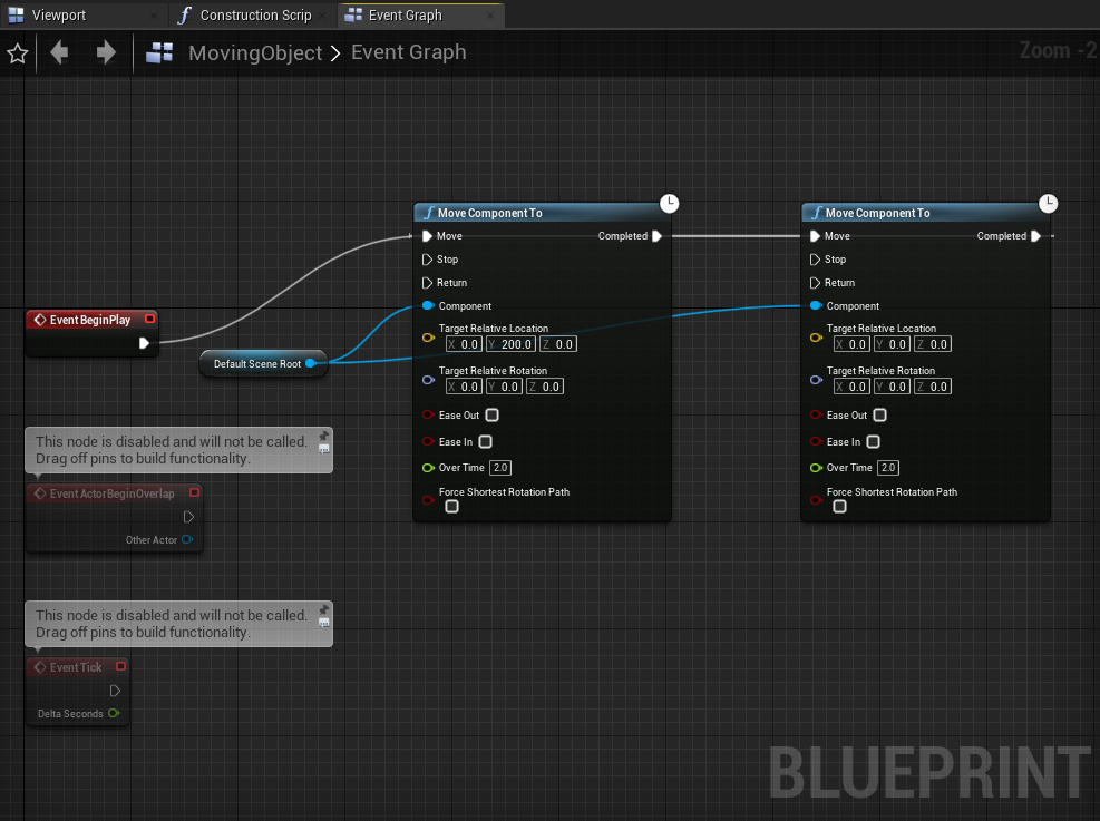
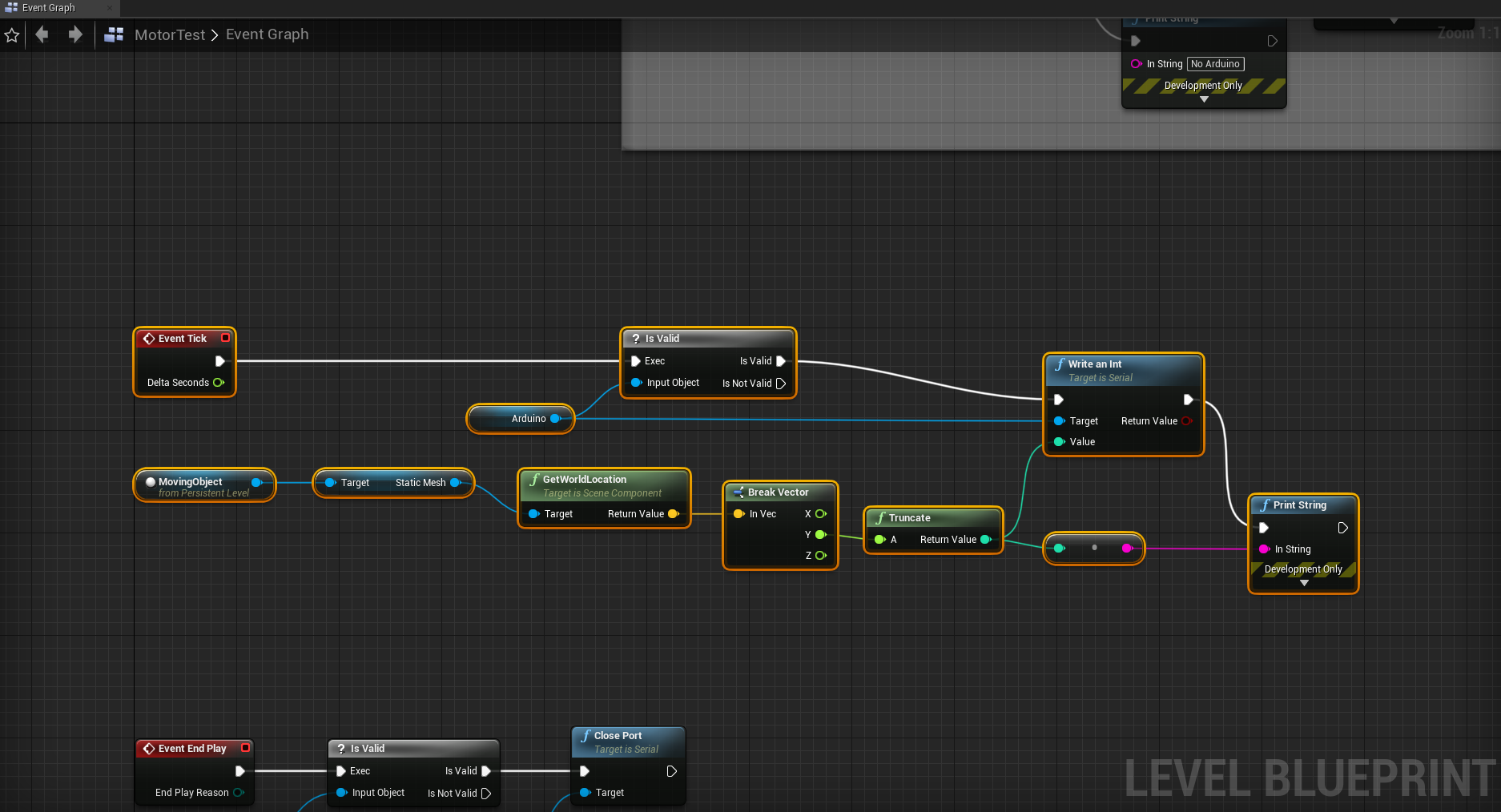
}The setup within UE4 was to make an example object move from position A to position B, and back. Using this controlled movement will give us predictable results on the Arduino, meaning we can determine if the information is being sent correctly. This is the UE4 set-up, excluding simple port opening/closing. If you are unsure how to do this, please see the previous blog posts for the node networks.
And this is the video of it working. Note the printed values of Y in UE4 and comparison with the LED illumination. Remember, the test case is LED1 triggered by values <50, LED2 triggered by values between 50-100, LED3 triggered by values over 100.
With this being established, it is pretty simple to send information as an Int through to the Arduino and store it within a variable. With some additional code on the Arduino, we may be able to send complex strings from the Arduino and decode them on the Arduino. Part of the challenge of communicating more complex information is that you can’t do it per line (i.e. multiple lines), as both the Arduino and UE4 operate on a per tick loop approach. Each individual line could be seen as another ‘tick’, and executed by the same code loop and generate overlapping information. If we could send a string which looks like ‘140,850,320’, we could potentially use the commas a means to split the string into X, Y and Z variables and use these to drive the motors using some math to calculate before/after values and determine how much the motor needs to spin to reposition the physical object. This will be the next focus of these projects.
To be continued…
The next stage is to create an Arduino circuit which drives a motor, and make some adjustments to the code to accomodate driving a motor. The basic understanding is in place, however I believe there may be some complexities to figure out, such as driving multiple motors, dealing with negative positions in 3D space, and translating the min-max positional values to the min-max motor speed/direction values on the Arduino. The next post will aim to get this functionality working to hopefully provide insight into how a prosumer motion control system may be assembled.


