
In my previous blog post titled ‘Arduino/Motor control from variables in UE4 – Part 1‘, I set up an animated object within UE4 and I used the Y positional values to send information to the Arduino to trigger lights at certain positions. Whist this wasn’t too complicated, it was a step towards sending specific values to the Arduino to make it perform a task, rather than single characters to trigger specific events, or reading flow data from the Arduino within UE4. One of the issues which I foresaw whilst setting up the Part 1 project was dealing with negative numbers. What if the object (camera for example) moves in a positive AND negative 3D space, how could that translate to the Arduino. I’m sure this is a simple answer for those with experience in C++ and UE4, however it is new to me so I needed to figure it out myself. This turned out to be not as easy a task for me to understand, but I’ll go through things within this blog post… Spoilers, we got there in the end!
Project Outline
To extend on the previous project, and to extend the functionality of the learning, I thought controlling a motor and its polarity may be a good way to potentially control a motion control rig. The project Zoetrope in the Arduino Projects Book on page 103 formed the basis of this project, where we used a H-Bridge to control a motor. The Switches and the Potentiometer in this project were removed as I wanted to drive the motor speed/direction with code directly, rather than a mechanical method. The aim of the project was to understand how to drive the speed and direction of the motor from UE4 values, including negative values to switch polarity of the motor. It was envisioned I could use the resultant motor control to drive a position of a camera in the physical space syncing UE4 camera position with physical camera position. To make things simpler, I used a pre-animated object and a single motor control/axis.
Problem Solving
Sending an Int from UE4 to the Arduino worked well for the previous project, as the values being sent to the Arduino were all positive values. When you try and send a negative value, it’s read as a positive value by the Arduino due to the Serial.read command – this is because as per the documentation: Serial.read returns ‘The first byte of incoming serial data available (or -1 if no data is available). Data type: int.‘ – what this means is, even if UE4 sends a value like ‘-123’, it’ll try and read the ‘-‘ as an int, and ignores it, as it isn’t an integer. To get around this, I attempted to send this as a String, however converting the String to a usable value for the motor was a little difficult. Sending the info as a char allowed the individual characters to be read, but stringing them together and converting them to a long or int was challenging. Admittedly, if I understood how to code in C++ better, I’d likely be able to resolve this much easier, however a lot of googling led me to pulling in a String, converting this to an int, and using the original string to find the first char and check to see if it was negative to set the motor direction/polarity. This solution isn’t much different from the previous project, however it requires a couple more steps – reading the String to look for a ‘-‘ and sets polarity of the motor, and converting the string to an int so the value is always positive. In essence, each value is independent, much like the way the H-Bridge controls the motor.
The Solution
This is the project in action. The Arduino setup appears to be VERY complex, however the complexity of it is based off an attached LCD – something I thought would be good to see what values the Arduino is receiving. I do have a stripped down version which works exactly the same, without the LCD display.
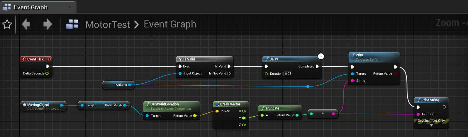
The base schematic of the UE4 looks something like this:
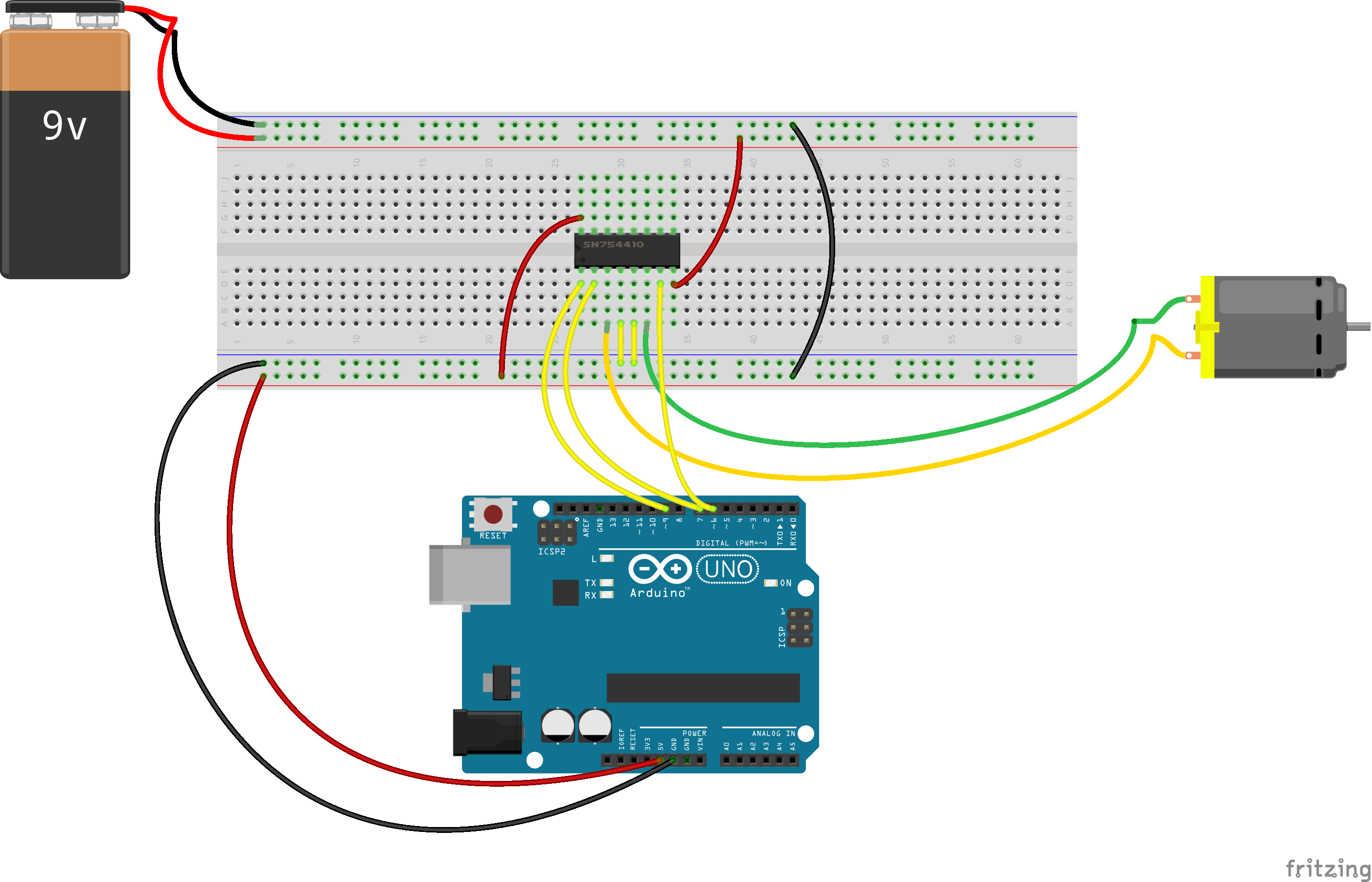
The motor is powered by an additional 9V battery, and controlled via the H-Bridge component. If you want to see how to leverage the LCD component to read values from the Arduino, the project within the Arduino Projects book titled ‘Crystal Ball’ on page 115 will show you how you can hook this up. The actual project setup looks like the following:

The setup within UE4 was very similar to the previous project, with an object animated to a position and then to a return position – in this case, we set one side to be a negative value, the other to be a positive value.

The main tick code sends a String via the serial, rather than an Int as per the previous project.
Code wise, there are a few more elements added to this Sketch to get it to read properly. The sketch can be found below, but I’ll highlight the key components of this sketch.
const int enablePin = 9;
const int controlPin1 = 6;
const int controlPin2 = 7;

int motorDirection = 0;
int motorSpeed = 0;

String readString;

void setup() {
  // put your setup code here, to run once:
  pinMode(enablePin, OUTPUT);
  pinMode(controlPin1, OUTPUT);
  pinMode(controlPin2, OUTPUT);

  digitalWrite(enablePin, HIGH);

  Serial.begin(9600);
}

void loop() {
  // put your main code here, to run repeatedly:
  if (!Serial.available()) {
    return;
  }

  while (Serial.available()) {
    Serial.setTimeout(6);
    delay(3);
    String UE4Value = Serial.readString(); //Read string from serial port
    motorSpeed = UE4Value.toInt();  //Convert string to int

    //If the original string starts with a negative symbol
    if (UE4Value.indexOf('-') == 0) {
      motorSpeed = motorSpeed * -1; //convert negative to positive
      motorDirection = 1;     //Set motor Direction
    } else {
      motorDirection = 0;
    }

    //Change direction of motor depending if value is negative or positive
    if (motorDirection == 0) {
      digitalWrite(controlPin1, LOW);
      digitalWrite(controlPin2, HIGH);
    } else if (motorDirection == 1) {
      digitalWrite(controlPin1, HIGH);
      digitalWrite(controlPin2, LOW);
    }

    //Set the motor speed
    analogWrite(enablePin, motorSpeed);
    delay(3);
  }
}
In the main body loop, the String is read from the Arduino. This string is converted to an int and assigned to the variable motorSpeed. A check is done on the original String from UE4 (UE4Value) to check if the index of the ‘-‘ is at 0 (first thing on the String), and if so, the direction of the motor (motorDirection) is set to 1. The motorSpeed int is also converted to a positive value so the analogWrite to the motor can use the value – done by multiplying by -1. If there’s no negative value, motorDirection is 0.
These motorDirection values toggle/invert the polarity of the motor, so it spins in opposite directions. This can be seen in the IF statement which tests value of motorDirection.
After this, the motor is sent the values of the speed with a delay. There are a couple of delays within this Sketch which are ESSENTIAL. This is at the start of the main body loop and at the end. Without these delays, I found the values being sent to the Arduino were sending too fast, and the Arduino would keep trying to set the speed but didn’t have enough time to actually perform the analogWrite to the motor. I found that with this setup, it worked for every value being sent, however with lower delays and timeouts, the program did not work. I also found that by setting the motorSpeed to 0, or disabling the motor in the !Serial.Available() check actually made the program not work. Ideally, I wanted to disable to motor when the Serial port wasn’t active, so it would naturally turn off when the program was terminated, however I found the motor would turn on and off instantly, like the Serial port was turning on and off at the end of each loop. Due to this, the motor did not have the momentum to maintain the rotation and would just ‘click’ on and off. By removing this, the program functioned correctly, however I would always need to reset the Arduino at the end of every run time (as you can see in the video). A half-assed solution I’m sure can be solved with more knowledge.
Conclusive Thoughts
There are a number of issues within this project which still need to be resolved. This includes:
- Not being able to disable the motor on exiting the application, without resetting the Arduino
- Values are not mapped yet to situations where the position in 3D space goes beyond -255/255 (the extents of the motor speed)
- Actually didn’t attempt to translate distance to rotation values/speed, which is needed to move physical objects – cannot communicate number of rotations of the motor, only speed and direction
- Motor contains momentum and therefore changes between + and – directions are not immediate
- Large jumps in values are problematic as the motor isn’t responsive enough
After some further reading and investigating, the standard DC motor being used wouldn’t be the best component to try and drive a positional value of a physical object to be pinpoint accurate, as there are a number of issues involved in this (including math being one!). A stepper motor will be likely more accurate, as you can specify rotation values therefore specify distance over time. The next project will involve simple stepper motors to understand how to use them, and how to match physical position with virtual position. This project wasn’t useless, as it helped me understand some more C++ Arduino code, and how to convert values to positive/negative and use H-Bridges. Adding to this, it also helped me understand how to use LCD displays. This project may be useful for a project where driving a virtual car also drives a physical car – never know what it can be used for!


